The AVR Microcontroller
The AVR enhanced RISC microcontrollers [1] are based on a new RISC architecture
that has been developed to take advantage of semiconductor integration and software
capabilities of the 1990's. A block diagram of the AVR architecture is given in figure 1.
The memory sizes and peripherals indicated in the figure are for the AT90S8414
microcontroller.Central in the AVR architecture is the fast-access RISC register file, which consists of
32 x 8-bit general purpose working registers. Within one single clock cycle, AVR can
feed two arbitrary registers from the register file to the ALU, do a requested operation,
and write back the result to an arbitrary register. The ALU supports arithmetic and
logic functions between registers or between a register and a constant. Single register
operations are also executed in the ALU.
As can be seen from the figure, AVR uses a Harvard architecture, where the program
memory space is separated from the data memory space. Program memory is accessed
with a single level pipelining. While one instruction is being executed, the next
instruction is being pre-fetched from the program memory.
Due to the true single cycle execution of arithmetic and logic operations, the AVR
microcontrollers achieve performance approaching 1 MIPS per MHz allowing the
system designer to optimize power consumption versus processing speed.
Figure 1: The AVR Architecture (AT90S8414)
The Architecture allows for up to 8M Bytes program memory, and 16MBytes of Data
memory, and covers a wide range of applications.
Fine tuning AVR
There are several advantages in using HLLs in stead of using Assembly language when
developing microcontroller applications. There has, however, traditionally been one
major disadvantage: the size of the code increases. The AVR microcontroller was
developed with the C language in mind in order to make it possible to construct a code
efficient C compiler for AVR. To improve this feature even more, the development of
the C compiler was started before the architecture and the instruction set were
completed. By allowing professional compiler developers at IAR Systems in Sweden
to comment on the architecture and instruction set, we were able to make a
microcontroller very well suited for C compiler generated code.
This section describes the modifications that were done in order to tune the
architecture and instruction set towards even more towards the C language.
Addressing modes
In order for the compiler to generate efficient code, it is important that the supplied
addressing modes matches the needs of the C language. The AVR architecture was
originally equipped with two pointer registers. These two pointers could be used for
indirect addressing, indirect addressing with post increment, indirect addressing with
pre-decrement, and indirect addressing with displacement, giving good support for
operation on pointers. In addition, there was a paged direct addressing mode for
accessing variables placed in the data memory.
Displacements
The indirect addressing mode with displacement is a very useful addressing mode, also
from a C compilers point of view. For example, by setting the pointer to the first
element in a struct, you can reach as far in the struct as the displacement allows
you, without having to change the 16-bit pointer. The indirect addressing with
displacement mode is also frequently used for accessing variables placed on the
software stack. Function parameters, and autos are often placed on the software stack,
and can be read and written without having to change the pointers. The displacement
addressing is also very useful in addressing elements in an array.
Even though the displacement mode is very useful in many cases, there was a problem
with the reach of this addressing mode. Originally, the displacement was limited to 16
locations, whereas the displacement needed in real applications often exceeds this
number. In the case where the location can not be reached by the displacement mode, a
new pointer needs to be loaded. To expand the reach of the displacement mode, we
needed to change other parts of the instruction set to get enough coding space. At the
same time, we were informed that the paged direct accessing mode was difficult to use
from the compilers point of view. By removing the paged direct addressing mode,
space was made available for expanding the displacement to 64 locations, which is
large enough to meet most demands for indirect addressing. The paged direct
addressing mode was changed to a two word unpaged direct addressing mode, see
below.
The number of memory pointers
The AVR microcontrollers were originally equipped with two 16-bit memory pointers.
From a C Compilers point of view, one of these pointers must be used as a dedicated
software stack, leaving only one memory pointer for general usage. In many cases, you
need to copy memory from one area to another. Having only one memory pointer, you
would need to read one byte, set the pointer to the destination area, write the byte and
then set the pointer back to the source data area. By including a third memory pointer
(with reduced functionality), data can be copied from one memory area to another
memory area without having to set the pointers. By exploiting the post increment
mode of pointer addressing very efficient loops can be constructed for this purpose
(assuming Z points to first byte in source, X points to first byte in destination):
LDI R16,0x60 ; Load byte count
loop: LD R17,Z+ ; Load byte, increment pointer
ST X+,R17 ; Store byte, increment pointer
SUBI R16,1 ; Decrement counter
BRNE loop ; Branch if more bytes
The possibility to post-increment and pre-decrement also makes the pointers very
efficient for implementing stacks. This is of course utilized in the software run-time
stack.
Direct addressing
As described in the displacement section, we originally had a paged direct addressing
mode which was difficult and inefficient to use by the compiler. Since we needed
coding space for an increased displacement, the paged direct addressing mode was
removed. It is, however, inefficient not having any direct addressing mode, since we in
some cases need to access variables placed in the data memory area. Especially when
dealing with static characters, the code overhead will be large (50%), since
static variables needed to reside in data memory and can not automatically be
placed in registers. In order to overcome this problem with inefficient code, we
decided to include unpaged direct addressing instructions taking a 16-bit address,
making it possible to address 64KByte data memory in one instruction. In order to
access such a large amount of memory, these instructions had to be two 16-bit words.
Using this addressing mode is more efficient than using pointers when the number of
bytes to be accessed is small, for instance when a character is read. For larger areas, it
may still be more effective to use indirect addressing (see example below).
Loading of a character:
Indirect addressing (6 Bytes): Direct addressing (4 Bytes):
LDI R30,LOW(CHARVAR) LDS R16,CHARVAR
LDI R31,HIGH(CHARVAR)
LD R16, Z
Loading of a long integer:
Indirect addressing (12 Bytes) Direct addressing (16 Bytes)
LDI R30,LOW(LONGVAR) LDS R0,LONGVAR
LDI R31,HIGH(LONGVAR) LDS R1,LONGVAR+1
LDD R0,Z LDS R2,LONGVAR+2
LDD R1,Z+1 LDS R3,LONGVAR+3
LDD R2,Z+2
LDD R3,Z+3
Zero flag propagation
In order to make conditional branches, a number of the instructions manipulates the
AVR status register, which consists of a number of flags. A conditional branch
instruction following such an instruction, will branch or not branch, depending on the
settings of these flags. The arithmetic instructions manipulate the flags, making it
possible to check whether a number A is smaller than, equal to or greater than another
number B. When the numbers in question are eight bit numbers, there are no problems,
since all the flags are depending on the flag setting done by one instruction only. When
using 16 or 32 bit numbers, which is common in the C language, the problem is
somewhat more tricky, since a 32 bit subtraction, for instance, is calculated as 4
consecutive 8 bit subtractions, and after each subtraction, a new set of flags is
generated.
For propagating the carry flag, most processors have incorporated instructions which
takes into account the previous setting of the carry flag, for instance SBC - subtract
with carry where SBC A,B means A=A minus B minus Carry-bit. There is however,
another flag that needs to be propagated in order to be able to correctly do all
conditional branches. This is the Zero flag.
Example:
A=R3:R2:R1:R0, B=R7:R6:R5:R4
We want to subtract B from A and jump to a specific location if A is equal to B. If the
Zero flag is only dependent on the last arithmetic instruction, the following sequence
will not do:
SUB R0,R4
SBC R1,R5
SBC R2,R6
SBC R3,R7 ; R3=R7 => Zero flag set
BREQ destination
since the flag settings present during the BREQ instruction only depends on the flags
set by the last SBC instruction. If the most significant bytes are equal, the Zero flag
will be set and the branch will be done, even if the 32 bit numbers are not equal. This
problem also applies to other conditional branches.
There are two ways of overcoming this problem. One is to save the flags produced by
each instruction, and then check all the zero flags after the fourth subtraction is done.
The other, more elegant way, is to propagate the zero flag in the carry instructions like
this:
Znew =Not(R7) AND
Not(R6) AND
...
Not(R0) AND
Zold
By propagating the Zero flag in this way, all conditional branches can be done after the
final subtraction, since all the rest of the interesting flags (overflow and positive flag)
are only dependent on the most significant byte.
Tuning the arithmetic instructions
Some tuning of the arithmetic instructions was also done. This tuning is described
here.
Addition and subtraction
We originally planned to have both addition and subtraction with eight bit constants -
ADDI and SUBI. We did, however, not have space for having Carry instructions with
constants, so a 16 bit add with a constant would look like this:
ADDI R16,0x44
LDI R18,0x55
ADC R17,R18
An addition can, however, be realized as a subtraction and vice versa, so it was
decided that the ADDI instruction should be changed to a SBCI instruction, thereby
enabling 16 and 32 bit additions and subtractions with constants, thereby reducing
code size substantially in 16 and 32 bit cases and with no code size penalty for 8 bit
cases.
Compare with constant
The original instruction set did not include any instruction for comparing a register
with a constant. In order to do such an operation, a constant had to be loaded into a
register, and then the two registers could be compared. This is a very frequently used
operation, and as a result of removing one of the original addressing modes, space was
found in the instruction coding for this instruction.
Non-destructive comparison
If you want to compare two eight bit numbers, then this can be done by using a
compare instruction. If you want to compare 16 or 32 bit numbers however, you
would originally have to compare use subtraction with carry in order to get the flag
setting right. The problem with using subtraction with carry is that it overwrites the
contents of one of the numbers you are comparing. One solution to this problem is to
copy this number over to new locations before subtracting, but such a solution will
require more instructions and will use more registers. In order to overcome this
problem, we decided to include a Compare with carry instruction, thereby enabling
nondestructive comparison of numbers larger than eight bit.


.jpg)


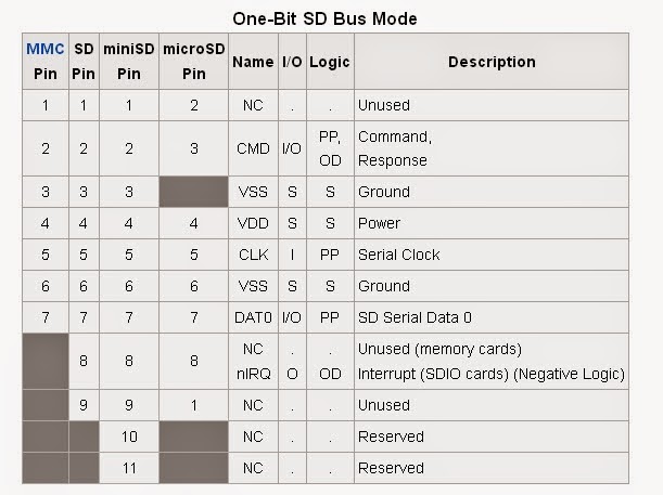
 Micro sd card pins are: